Articles & Video

Technical Rescue

Tree Anchor “Ratings” Based on Wind Loading

The following has been re-posted by Animal Fire Rescue for educational purposes.

The original post can be found at: https://rigginglabacademy.com/what-if-trees-had-ratings-in-kn-tree-anchor-ratings-based-on-wind-loading/

Tree Anchor “Ratings” Based on Wind Loading

From John Morton for ITRS: What if Trees Had Ratings in kN? Tree Anchor "Ratings" Based on Wind Loading

What if trees had ratings? What an amazing concept. John Morton, an engineer-scientist-visionary-technician, has been doing canopy studies for years and knows how they are affected by wind. Trees, whether alone or in community, are all influenced by wind and all have a certain “wind rating” to them. When SAR members show up on scene, and these trees are the “anchors of life”, it’s best to know what you working with, right? John does an amazing job at bringing an illuminating view to this concept in his study, “What if Trees Had Ratings in kN?: Tree Anchor ‘Ratings’ Based on Wind Loading”. We hope you enjoy this study as much as we did.

Rigging Lab Academy is all about sharing the story of this planet’s Thought Leaders, and what John has to say is important. The following study was presented by John Morton at the International Technical Rescue Symposium (ITRS) in November 2015. For the full slides of this presentation, courtesy of ITRS, click here.

About John

Since 1999, John Morton has been a technical rescuer with Snohomish County SAR and Everett Mountain Rescue in Washington State. Along with hundreds of rescue missions, John has been an instructor for many basic rescue topics through the years (medical care, fieldcraft, search tactics, working in terrain, etc.). More recently, he spends more time instructing in our technical rescue specialties (rope, water, helicopter). John has been a SAR rope rescue instructor since 2001, and lead rope instructor since 2004. Beginning in 2001, John has been an active member of Snohomish County’s Helicopter Rescue Team, flying as “first out, last back in” Helicopter Rescue Technician. Through the past decade, John has been serving as team leader for our SAR Water Rescue program, including as evaluation hovercraft pilot and as one of our Rescue Swimmers. Beyond rescue work, John is also an avid paddler and sea kayak instructor. And trail running, and skiing, and a few others. When not doing rescue work, or paddling, or working with his trees, John has a little side gig doing airplane and spacecraft design work as an engineer at Boeing.

What if Trees Had Ratings in kN?: Tree Anchor “Ratings” Based on Wind Loading

When technical rescuers arrive at a scene that may involve rope access, among the first things we do is evaluate potential anchors for useful location and adequate strength. Most us have been taught (and then perhaps repeated as instructors) that adequate anchors are foundational to a safe and effective rope rescue system. Most of us have been taught (and then perhaps repeated as instructors) that a living, well-rooted tree is an adequate rescue anchor, provided the trunk is helmet-sized or larger. Specifically, a helmet-sized tree has sufficient strength to withstand forces we might apply via our rope system.

Ideally, it would be convenient if each tree had a carabiner-like “strength rating” placard clearly indicating how much anchor loading that tree is known to withstand. While we are dreaming, it would be even better if that tree’s load capability were demonstrated by testing, since trees do not have tight manufacturing controls. Rather than a test-based strength rating, trees just have this often-repeated “rule” that helmet-sized is strong enough. But is that really all we have to judge tree strength?

People who spend time outdoors will sooner or later witness a group of trees bearing the onslaught of a powerful windstorm. When we watch our wooden giants getting rocked by the wind gods, it is a compelling and humbling reminder of the small scale we humans typically experience. A technical rescuer might watch such a wind storm and think something like, “Wow, those trees are handling forces far, far beyond anything we can bring to bear using our puny little rope systems.” Hmmmmm…

How much wind would a tree need to withstand to show itself adequate to carry equivalent loading that might be applied through a rescue anchor? That probably depends on the type of tree. And how tall is the tree. And what nearby trees deflect some of the wind. And soil conditions. And terrain. And root structure. And perhaps other things that might be difficult to nail down.

When technical rescuers arrive on scene, we can be confident of two things about a living, standing tree: 1) the tree has been exposed to some amount of wind, and 2) the tree has been able to withstand the forces resulting from that wind. If our rescue teams had some method to translate a tree’s strength that has already been proven by wind into equivalent anchor strength (a “wind rating”), then we could make a reasoned decision about using or not using a candidate anchor in our rope system. More anchor choices. Favorable placement for rope alignment. Less rope stretch using anchors closer to the edge. Faster setup. These and other reasons motivate us to consider the widest array of credible rescue anchors.

But to be practical, a method to determine “wind rating” would need to be appropriate for field use. It would need to work with a range of rescuer fluency, and when applied under the time pressure, weather, fatigue, and life safety conditions that define our missions. Anchor selection during a rescue cannot deteriorate into scientific research on scene. No committees. No magic. Plenty of margin. Certainly, this method includes some complexity: mechanical engineering, and numerical modeling, and meteorology (weather), and dendrology (trees), and perhaps some testing (measure and break things). However, the objective of this project is simple: develop a mission-appropriate method that gives go/no-go adequacy of “smaller” trees for use as rescue anchors.

Understanding How a Tree Tells Us What Anchor Strength it Has

Long before our rescue teams arrive to consider a tree as a potential rescue anchor, that tree has been exposed to a variety of natural forces. Depending on climate, a surviving healthy tree will have tolerated effects of wind, precipitation, snow loading, impact from tree or rock fall, etc. As a surrogate for forces applied by a rescue anchor, wind force has the advantage of imparting substantial bending/shear load, much like a rescue anchor would apply. Also, characterizing wind loading on trees can draw on techniques related to predicting wind effects on man-made structures, such as skyscrapers or antennae.

The heart of this project is a force model that has three key elements:

  • Determine how much wind reaches a particular sized “smaller” tree.
  • Determine the force applied to a tree by the wind that reaches it.
  • Translate force from wind into equivalent force applied by a tensioned rescue anchor.

Three additional elements enable the force model and compile useful results:

  • Establish an aerodynamic profile for trees that are anchor candidates.
  • Calculation tool to examine a range of tree size, over a range of wind speed, for many tree species.
  • Produce results that can be consumed by rescue teams, including during an active mission.

Previous work has established that detrimental effects on trees used as rescue anchors are primarily related to bending and shear load that compromise the base and root system. Other theoretical failure mechanisms, destruction of the wood itself, for example, are not what limits our ability to use a particular tree in a rescue system. Rick Weber, “How to Determine Tree Strength”, ITRS 2010.

Turbulence Model: How Much Wind Reaches a Smaller Tree?

From John Morton for ITRS: What if Trees Had Ratings in kN? Tree Anchor "Ratings" Based on Wind Loading Picture 1

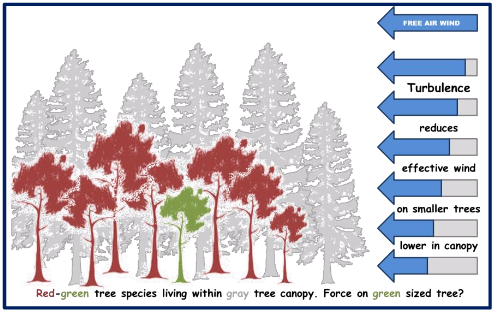
Modern weather-related data gives fairly thorough indication of wind throughout a region. Example access points might include National Weather Service websites, Weather Underground, and various aviation weather resources. During seasonal high wind events, the upper end of sustained wind speed is shown here as “free air wind” speed. Wind speed in free air is related to, but not the same as the wind that impacts smaller trees within a canopy. Lower in the canopy, wind speed, and the resulting forces are reduced as the moving air becomes turbulent.

In addition, the speed of turbulent air varies within the canopy, such that the wind speed towards the top of a mid-sized tree is not the same as further down that same tree. Finally, a tree species may be intermixed with other taller species, so that the canopy is determined by trees taller than a full-sized example of the species under consideration. For purposes of force calculations in this model, turbulent wind below the canopy is “sliced” into decreasing wind speeds moving lower in the canopy.

Aerodynamic Profile: Representing a Tree as a Stack of Spindled Cylinders

There is considerable variation among individual real-world trees–even of trees of a single species. For this wind force model, a species tree is simplified as a representatives tack of 20 cylinders on a spindle anchored at its base. Each cylinder represents 5% of the tree height, but is narrower than the tree outline in order to conservatively address variation among individual trees. In the crown portion of the tree, the diameter of the cylinders are well within the tree outline to represent wind passing through branches with comparatively less force on the base.

From John Morton for ITRS: What if Trees Had Ratings in kN? Tree Anchor "Ratings" Based on Wind Loading Picture 2

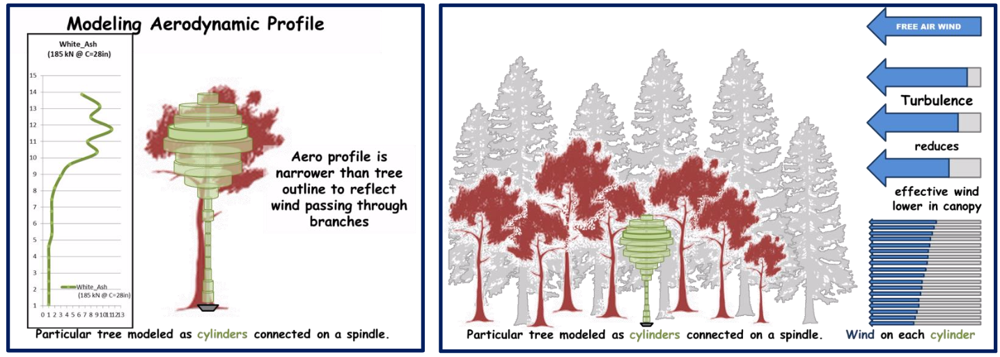
Tree species data in the model also include a relationship between base circumference and tree height, as well as canopy height of neighboring species. Where there is variability, such as canopy height of neighboring species, profile data are chosen conservatively. Tree shape parameters and information about neighboring species (canopy) are drawn from references such as United States Forest Service Silvics Manual, and the Audubon Society Field Guide to TREES.

Engineering Magic: Calculating Wind Force on Cylindrical Structure


From John Morton for ITRS: What if Trees Had Ratings in kN? Tree Anchor "Ratings" Based on Wind Loading Picture 3
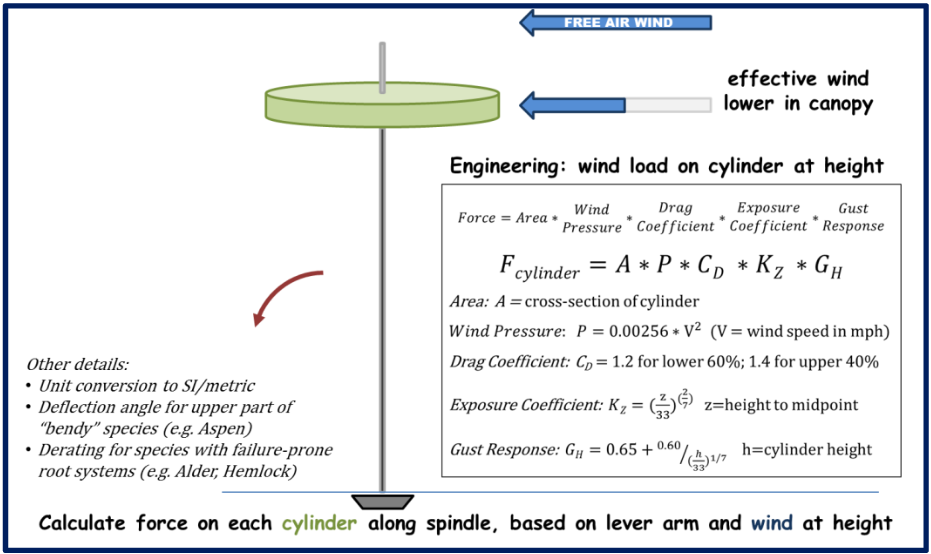
Once a turbulent wind profile and aerodynamic tree shape are established, they are aligned at ground level. Then force is calculated for one cylindrical segment at a time. Wind loading on a cylindrical body at height (reacted at its base) is well understood from design of skyscrapers and antennae. While the calculations have somewhat complex exponential terms, the relevant formulae are readily available, even just a Google search away. Here’s one example, among many.

The base of the tree carries wind load accumulated over the entire tree length, demonstrating the tree’s ability to carry bending and shear force. This is the same load carrying capability we rely upon for a rescue anchor.

Mechanics: Translate Wind Force into Equivalent Anchor

Perhaps the most straightforward part of this project is translating force applied to a tree at height to an equivalent force applied at the location of a rescue anchor. This translation is calculated segment by segment, using techniques that would be familiar to a mechanical engineering student.

From John Morton for ITRS: What if Trees Had Ratings in kN? Tree Anchor "Ratings" Based on Wind Loading Picture 4
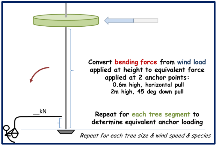
It is worth noting that these calculations correlate wind force over the entire tree length to an equivalent anchor force applied horizontally at a height of 0.6 meter (2 feet). This is deliberately not as low as a rescue anchor could be placed on a real-world tree. Moving an anchor lower on a tree provides on-scene rescuers an option that adds margin beyond these results. Depending on risk factors, placing an anchor very low on a tree may allow responsible use of an anchor that calculates as “marginal” at 0.6 meter anchor height.

A similar set of results is compiled that correlates wind force over the entire tree length to an equivalent high directional anchor force applied 45 degrees below horizontal at a height of 2 meters. Once again, this is conservative as a typical high directional pulls more vertically than 45 degrees. Here also, on-scene rescuers have the option of placing high directional anchors lower than 2 meters if that helps a marginal strength tree.

Number Crunching: Repeat for Each Tree Segment, Tree Size, Wind Speed, Species

It would be possible to hand-calculate the turbulent wind profile under a species canopy, then identify the resulting wind impacting a “modeled tree” cylindrical segment of particular height and diameter. Then one could calculate the wind forces applied at the lever arm that is the height of the cylinder above the ground. Possible, but tedious to hand calculate.So, we will leave that to the computer.

This project includes a rudimentary computer program to repeat the wind loading calculations for 20 segments per tree. Then the cycle is repeated for each increment in tree circumference for that species. Then that entire calculation for various tree sizes is repeated over a range of free air wind speed. Then the size/wind speed cycle is repeated for each tree species of interest.

As the calculations repeat for increasing tree circumference, the 20-segment aerodynamic tree model is scaled accordingly. This extends the slightly taller tree model higher into turbulent wind, as well as exposing slightly wider cylinders to that wind. Both factors tend to drive increased wind force, though the relationship is not linear – for example, a 2% increase in tree size results in more than a 2% increase in force applied to the tree.Likewise, a 5% increase in wind speed results in more than a 5% increase in force applied to the tree. The details are complicated but manageable in small steps.

From John Morton for ITRS: What if Trees Had Ratings in kN? Tree Anchor "Ratings" Based on Wind Loading Picture 5

As the calculations repeat for each wind speed, the turbulence model is adjusted and calculations repeated over the range of tree sizes (circumference in inches). As the calculations repeat for each tree species, the associated canopy determines the turbulence profile that applies.

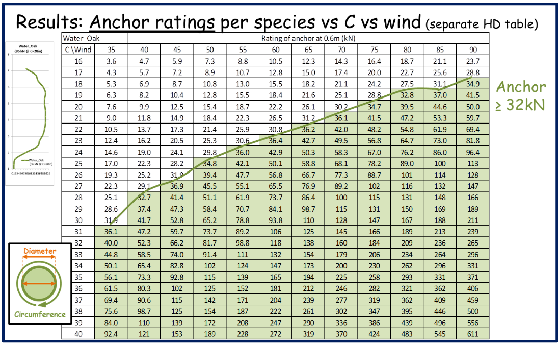
For each tree species, the calculations result in two tables listing anchor strength values for a range of tree size and wind speed. One table is for a horizontal rescue anchor set at 0.6 meters, and another table for high directional set at 2 meters and pulled 45 degrees below horizontal. From these force data, a variety of tables and charts are built to be applied by rescue teams.

Results: Collect the Data in Various Formats, Including Field-Deployable Guides

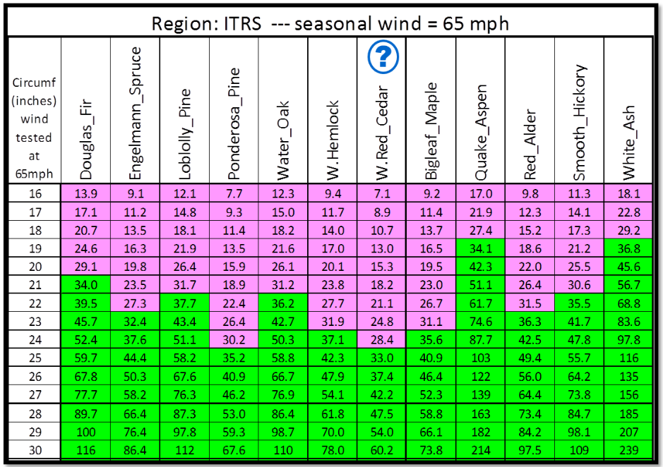
The model output collects results for up to 12 tree species per designated region. Results include material that enables“sanity checks” –data not intended to be field deployable. One example shows full-strength anchor size vs wind speed for 12 tree species (below).

From John Morton for ITRS: What if Trees Had Ratings in kN? Tree Anchor "Ratings" Based on Wind Loading Picture 6

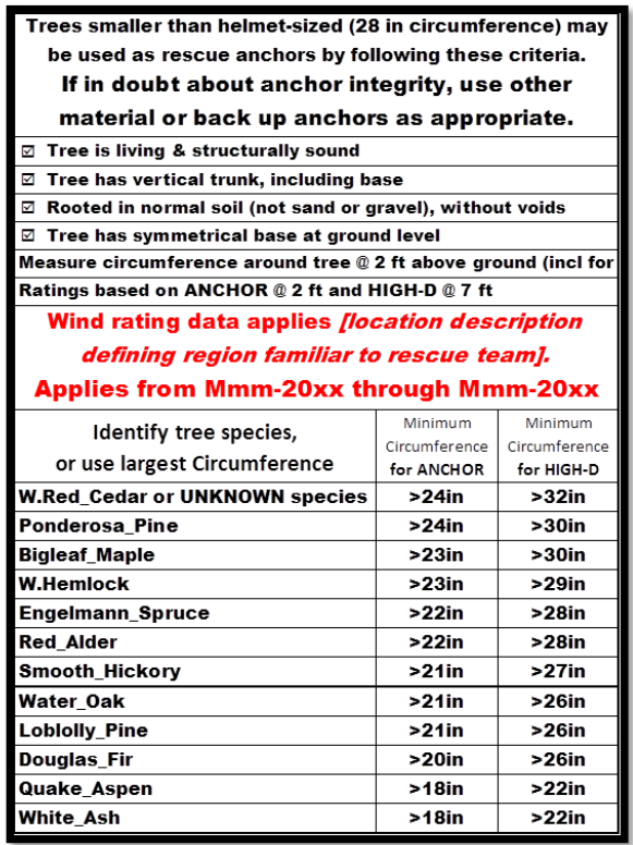
But the most valuable results are pages that can be included with field gear that enables rescue teams to make go/no-go anchor decisions on scene (below).

The inputs required to produce region-applicable “field guides” include free air wind speed (typically upper end of sustained wind during storms) and also the threshold of choice for rating of a “full strength” rescue anchor.

From John Morton for ITRS: What if Trees Had Ratings in kN? Tree Anchor "Ratings" Based on Wind Loading Picture 7For the purposes of illustration, these results show a fictitious “ITRS2015 region”, which includes a sampling of trees from across North America. To create sample field guide pages, these results were run with a “rating” of 65 mph as free air wind speed, and 32 kN as threshold for a full-strength anchor. Note that these inputs do not affect the tree or wind models, nor on the force calculations for various sized trees. Rather, these fully-adjustable inputs only determine which results are collected into field guide pages.

There must be some time element to these results. Wind that a tree was exposed to 10 years ago is not a compelling indicator of that tree’s strength today. In the Pacific Northwest, our seasonal wind events are typically in December through March. Our SAR team expects to update these field guide pages each spring, based on winds during the preceding months. Then the results are considered valid for about 1.5 years (through two summer rescue seasons).

It is important to note that wind rating values do not indicate true breaking strength of a tree. Rather, they show an anchor force the tree can withstand based on wind forces the tree has already withstood. A tree may be considerably stronger than these values suggest. This is particularly true for triangular-profile trees, such as Western Red Cedar. These have a fairly thick trunk for their height, and most of their sail area is low to the ground.For example, in the same wind storm, wind force on a 20-inch circumference Red Cedar would be less than a 20-inch White Ash. Yet the Red Cedar may, in fact, be stronger than the same sized White Ash, just not as thoroughly tested by wind forces. While the additional strength beyond the wind rating is difficult to quantify, the margin is in the direction of safety.

From John Morton for ITRS: What if Trees Had Ratings in kN? Tree Anchor "Ratings" Based on Wind Loading Picture 8

To be useful, this method to determine “wind rating” needs to be appropriate for field use during a rescue mission. It needs to work with a range of rescuer fluency, and when applied under the time pressure, weather, fatigue, and life safety conditions that define our missions. It has to be repeatable by different team members and on different days. It has to fit into normal team training.

Printed on two sides and laminated, this field guide has a simpler side, and an almost-as-simple reverse side. Using the super simple front side, a rescuer armed with the laminated page and 3-foot tape measure can consistently determine go/no-go for a prospective anchor tree. The ability to distinguish species improves tree options, but is not critical to consistent go/no-go decision.

Using the reverse side, and armed with the tape measure, a sharpie, and some pink and green flagging, a team could send New Guy ahead to measure and label candidate anchor trees in the operational area. Flagging would indicate go (green) vs no-go (pink), as well as strength ratings in kN. This would literally result in anchor trees having the physical equivalent of a rating stamp like a carabiner or pulley. More practical for a real rescue mission, an individual tree’s “wind rating” could be looked up, so that anchor decisions can be made in seconds (use it, back-tie, multi-point, don’t use it).

Critical Thinking: Do the Model Results Seem Reasonable?

Based on extensive pressure testing, this wind force model yields consistent and sensible data. The results compare well to analytical and test data, make sense when comparing one species to another, and also fit anecdotal experience using smaller trees as rope system anchors. As I have previewed the model results with experienced technical rescuers, several questions are frequently asked.

Q: Why 20 tree segments, rather than more or fewer?

A: I tried as few as 12 segments for trees, with marginal results as tree shape nuance had noticeable effect on results for a given wind speed. I also tried more detailed profiles such as 30 or 40 segments. These aero profiles are more difficult to create, yet had little effect on results, compared to 20 segments.

Q: How do model results compare to testing?

A: Rick Weber’s work presented at ITRS-2010 is an example of past study and testing showing tree anchors into the 15 kN range. This is excellent data, and responsibly tops out when real-world forces begin to pose problems during testing. Once calibrated for anchor height, these test data line up very nicely with model results described here. Such alignment is not conclusive, but it is compelling.

Q: Does this mean rescuers need to learn tree species identification to do their job?

A: If rescuers cannot identify the species of a candidate anchor tree (limited by time or expertise), simply use the species marked to represent “UNKNOWN” (Western Red Cedar in the example set). Identifying tree species allows the rescuer to take full advantage of the tree under consideration, rather than simply using the species with the lowest strength rating on the list (safe but conservative).

Q: What areas of the model are still uncertain, yet have significant effect on the results?

A: Model results depend significantly on the turbulence profile. The current turbulence model shows wind speed decreasing below canopy more than is probably real, which is conservative. I have both model improvements and testing in mind that might allow peeling back some conservatism, which would “turn green”slightly smaller trees as credible rescue anchors. But the differences are small, perhaps an inch or two at most in circumference. A bit of conservatism is not so bad in this technical rescue business.

Conclusion: A Healthy Tree Tells Us About the Anchor Force is Can Withstand

For regions with only light seasonal wind, limiting anchor selection to helmet-sized or larger trees is reasonable, but conservative. Using 28-inch circumference as a go/no-go criteria means that fully adequate trees would not be used. The overall rescue system may then be less effective, and less safe, for having bypassed potentially better-placed anchor trees. In areas with higher seasonal wind(wind storms greater than 45 mph), even smaller trees can be credible rescue anchors, based on having survived wind loading.

This model offers results that protect system integrity while being practically deployable in the field. These results are consistent with test data. Testing to failure is quite reasonably limited to modest forces for reasons of safety and practicality. This method extends results from field tests on small trees up to somewhat larger trees.

As always, decisions during rescue operations must align with training and field-appropriate tactics. NO SCIENCE PROJECTS DURING RESCUE MISSIONS! If teams intend to use smaller trees as rescue anchors, then practice how to do that responsibly.

The usual ITRS caveats apply here:

  • More testing and research is good.
  • Carefully consider new data, and apply it prudently.
  • Do the right thing for your team and your mission.

If my compatriots in the technical rescue community have questions, suggestions, criticisms, or want data for particular tree species, feel free to contact me:

John Morton
Snohomish County Search & Rescue/ Everett Mountain Rescue
Email: water-rescue6@scvsar.org

Authors Note: The tree anchor strength model described here first began as a joint project between myself and Mark Miller, of Ouray Mountain Rescue and Rigging for Rescue. Mark is well known in the community of climbers, guides, and technical rescuers, including among those who frequent ITRS events. Ironically, I was working on the presentation of this material for ITRS-2015, when I received the tragic news that Mark had been killed in a fall while ice climbing. So, while Mark was part of the early work portrayed here, he was not able to review the material presented at ITRS. This is the very least among many impacts from losing our brother Mark. – JM

Technical Rescue

The importance of proper training

The following has been re-posted by Animal Fire Rescue for educational purposes.

The original post and video can be found at: https://www.firerescue1.com/firefighter-training/videos/reality-training-the-importance-of-proper-training-omh7bP39geX5FdWR/

Reality Training: The importance of proper training

Firefighters become concentrated on doing things quickly rather than correctly when tasks are timed. Chief Wylie breaks down key training points in order to keep firefighters safe.

https://www.firerescue1.com/firefighter-training/videos/reality-training-the-importance-of-proper-training-omh7bP39geX5FdWR/


Technical Rescue

A Set of Fours: The SMC Advance HX Haul System

The following has been re-posted by Animal Fire Rescue for educational purposes.

The original post can be found at: https://rigginglabacademy.com/a-set-of-fours-the-smc-advance-hx-haul-system/

A Set of Fours: The SMC Advance HX Haul System

I have enjoyed the AZTEK for many years.  I have even, at one point in time, used 8 AZTEKs to build and set the truss system on our original RRG office building in Sisters (they toppled over and I had to re-align them and straighten out the building itself). Over the years, there have been improvements and the addition of the Omni Block pulley (moving for the the AZTEK Pro to the AZTEK Elite) was a good move. But still, I still needed an instruction book to deal with prusiks. Admit it…! Most of you have the same dilemma but won’t say anything :).

On a practical level, how many people actually change out their prusiks like they should?  What about inspection, much less changing them out?  How many people actually know which rope the prusiks go on?

Well, there are other options for a “set of fours” and the SMC Advance Tech HX Haul System is one of them. Yes, we will be discussing others, but this one is a keeper.  We’ve used many times for heavy set rigging (hundreds of pounds of 10″ x 20′ logs) for building platforms, as well as for general use jigger/piggy-back and tie-back systems.

In short, The SMC Advance Tech HX Haul System provides an extremely strong and versatile haul system. Weighing around 3 pounds, this kit is pre-rigged as either a 4:1 or 5:1 mechanical advantage system.  We’ve been using this system for a number of years now and have enjoyed it.  And as many of you know, I am have never been excited about having to deal with prusiks with a jigger system.  I just think it is backward thinking.

This system is smooth and strong and with Rich Delaney’s “Fast Fours” setup, it is even better for confined space/tight space rescues.

I’ll spare you the details as honestly… they are all great (AZTEK, Advanced Tech, HaulBiner ect…).  The Advanced Tech HX is NFPA 1983, and what this really means ?… It is strong!  When used properly per manufacturers specs, it will literally save you time, energy and money.  You’ll love it.

Cam Rating 4:1 Haul System Strength – Typical 4:1 system rigged using the Advance Tech HX with cam engaged on the 4th leg and a standard double Pulleys.  The system utilized the becket on the Advance Tech HX Pulleys.  System was pulled end to end using carabiner holes.

Cam Rating 4:1
     Rope ø      Breaking Strength
7mm 2,000 lbf. (8.9kN)
9mm 2,500 lbf. (11.1kN)
12.5mm 4,500 lbf. (20kN)

Cam Rating 1:1 Haul System Strength – This configuration is not recommended due to the relatively low strength results, but are included in these instructions to provide the necessary guidance when developing rigging methods.  Single rope strand is rigged through the engaged cam and over one sheave.  The force is applied between the end of the rope and the Pulleys carabiner hole.

Cam Rating 1:1
     Rope ø      Breaking Strength
7mm 500 lbf. (2.2kN)
9mm 700 lbf. (3.1kN)
12.5mm 1,000 lbf. (4.4kN)

Peace on your days…

Lance

BUY the SMC Advance Tech HX Pulley System

The SMC Advance Tech HX Pulley is a double pulley with an integrated cam that provides immediate progress capture without the need of prusik loops. The all in one frame and cam design presents a compact form factor. Stainless pins retain the rope when a rigged system is packed so that system can be pulled out and used immediately. Manufactured from high quality aluminum and anodized to help prevent corrosion. The Advance Tech HX is the most advanced pulley of its kind on the market today. The Advance Tech HX will support ropes diameters from 7mm up to 12.5mm. The Advance Tech HX is ideal for all rescue applications where a small mechanical advantage system is being utilized.


Wildland Fire

Be A Hero To Your Horse: Proactively React To Wildfire Danger

The following has been re-posted by Animal Fire Rescue for educational purposes.

The original post can be found at: https://thehorse.com/136151/be-a-hero-to-your-horse-proactively-react-to-wildfire-danger/

Be A Hero To Your Horse: Proactively React To Wildfire Danger

Rebecca Gimenez shares tips for preparing for a wildfire evacuation.

Favorite

Be a Hero to Your Horse: Proactively React to Wildfire Danger

Today I got a note from a reader in the West who boards her horse and is trying to be prepared. Stephanie Nicole said, “Just last week I got called ‘paranoid’ and other mean comments for wanting to be prepared. I’m the only person in a boarding stable of 40-plus horses with any sort of emergency plan. I got laughed at for putting shipping boots on a horse then going 10 minutes down the road. I’m the resident ‘safety freak’ but we’ll see who’s laughing when my horse is alive and safe when something happens!”

The main theme of this blog is to learn from the successes and failures of others in similar situations and scenarios that boggle the mind’s ability to understand them. Wildfires can happen anywhere in the world, and they move very fast. In this post, we will only discuss wildfire evacuation planning, since shelter-in-place planning is extremely dangerous and very difficult in wildfire situations.

We know that firefighters and weathermen have been predicting wildfires in the Western United States would be worse than ever this year due to years of drought, buildup of forest fuels, and increasing numbers of people living in the wildland/urban interface. State animal response planners in the Western states have been warning peopleto come up with an evacuation plan for themselves, their properties, and animals before the disaster comes.

This week more than 100 fires are burning in the United States, and people on social media and online news sources are sharing photographs of numerous horrific situations in which horses (and other livestock and animals) have died in trailers during evacuate attempts made too late videos of people leading horses out on foot and next to vehicles; livestock and horses trapped in fenced areas that died of smoke inhalation; and numerous other small and large situations that indicate a failure to evacuate or entrapment. Note: Don’t just lead them out of the barn and let them go, as even wild horses get killed in an area where they live and know their way around.

Other examples of failure to plan include owners leading their horses down main roads or interstate evacuation routes. These last-minute methods only demonstrate the lengths to which desperate people will go to try to save their animal and confirm that most people fail to plan ahead. These are not heroes–they are people who failed to plan, failed to prepare, and failed to execute well. In previous generations these failures would have been looked upon negatively in our generation, it makes the media.

Evacuation plans should be a part of the owner’s annual review of disaster mitigation strategies for a facility and absolutely must be reviewed when wildfire season begins. In several news stories this wildfire season, the real heroes are proactive people like Stephanie who plan ahead and ensure they can get their horses, kids, dogs, and valuables out ahead of time. In the military we have a phrase “leaning forward in their foxhole” another words, people who are situationally aware and ready to execute their plan.

It’s not the fire department’s job to come “save” you and your animals if you do not plan ahead. Be able to evacuate on your own efficiently and safely. Prevention, mitigation, planning and taking responsibility for your animals should be the theme of animal ownership. An all-hazards approach minimizes emergencies, injuries to animals, and losses. Count the number of horse trailer stalls you have in your trailer. That’s the number of horses you can evacuate. Now, count the number of horses you have on your facility. Did you have to swallow when you realized the point? You will not have time to come back for a second or third load of horses unless you evacuate extremely early and before evacuation orders are mandated.

It’s not the flames that kill horses or people, so don’t wait until the fires start creeping up on you to make your evacuation plan. Normally it is not the flames of a wildfire that will cause you and your horse to need to evacuate but instead the thick black smoke filled with toxins and poor air quality that impact you well before the flames get to your location, sometimes from miles away depending on ambient environmental factors (humidity, wind direction, speed, etc.). Toxins released by burning can severely damage to the lungs of any living organism. Carbon monoxide and carbon dioxide are common byproducts of fires and, when inhaled, block the absorption of oxygen at the level of the hemoglobin in the blood, causing asphyxiation through anoxia. Flames do not necessarily need to be visible for this to occur. Animals removed from wildfire affected areas may appear medically stable for days, then crash with severe pneumonia. Owners should consult a veterinarian immediately for aftercare because of airway complications from smoke and toxic fumes.

  • Be ready before the fires come with your truck hitched to the trailer, all relevant equipment loaded, extra water and forage, and vehicle prefueled. Experienced people in wildfire areas always have their trailer hitched and pointing out the driveway so that they don’t lose time if a fire sparks close to their facility.
  • Teach your animals to be reliable loaders in horse trailers or other transportation equipment is an excellent prevention mechanism to facilitate evacuation.
  • Teach your boarders, children, and family members what to do and where to meet if fire threatens. This will be specific to your facility but you don’t want to lose time looking for people or pets. What is your alarm call? Who does what?
  • Identify an alternate place to put your animals ahead of time, many miles away and out of the response zone where they will be less stressed and can reliably be fed and watered. Call friends and make a reciprocal agreement. For regional wildfire disasters, have a pre-coordinated evacuation facility in another state where you can take the animals.
  • Identify more than one route away from your facility in case roads are closed or blocked by fire progress. Horse trailers always need to be among the first to evacuate, because it will take you longer to drive the same route and you do not want to be stuck in traffic with your horses in the trailer.
  • Purchase a NOAA weather radio and listen to it at all times. Download the apps to your phone that allow you to track fire concerns in your area and evacuation warnings. Pay attention and check several times a day to maintain awareness of fires close to you.
  • Write down your plan for your facility for evacuation. Now, practice that plan, it is recommended that owners practice once a quarter as a matter of routine. Think you can do evacuate all your horses in just 30 minutes? Time it. You will scare yourself the first time with how long it takes, but practice makes perfect. Public facilities and boarding barns should practice a fire drill and review the evacuation plan once a month which ensures new boarders, employees and students are well prepared. Practice your evacuation plan to find the weaknesses within it. Note: The planning process is as important (if not more important) than the plan itself, involving all affected people as a team in generating the plan (family, employees, friends, boarders, etc.). This ensures commitment by everyone to the effort. This kind of training and preparation makes employees and family members more self-reliant, efficient, and confident if a disaster or emergency occurs.
  • Now that you have tweaked the issues, your facility should post the evacuation plan for wildfires where everyone can read it and see it easily. Tip: Insurers or the local fire department will walk through facilities and barns with owners to identify hazards and give suggestions for reducing fire risk. Make an appointment with the local fire department to come out and get involved, they are the professionals that can point out individual problems to consider with prevention and mitigation

Preparation,prevention, and planning are all things that we know we should do but tend to push off to deal with more short-term deadlines and responsibilities. From your horses’ perspective however, there is nothing that is more incipient than his/her safety and comfort. The responsibility of ownership extends to facilitating an evacuation plan for your animal(s), as much as it does to providing shelter, food, and water.

I welcome your comments and stories of evacuation successes and disasters here. Please share below.

ABOUT THE AUTHOR

mm

Rebecca Gimenez Husted, BS, PhD, is the primary instructor and president of Technical Large Animal Emergency Rescue. Her first book, Technical Large Animal Emergency Rescue, was published in 2008. She is an internationally sought instructor in technical rescue techniques, procedures, and methodologies, and she has published numerous critiques, articles and journal submissions on horse safety, technical large animal rescue and horse handling issues.

Heavy Rescue

5 steps to extricate patients from modern vehicles


Rip and blitz challenges: Use your cutter/spreader for car side removal extrication

Mar 4, 2020


You arrive on scene, and you’re confronted with a 2017 four-door sedan that has been T-boned by another vehicle. Victims are entrapped in both the front and rear seats, and you need full access to the damaged side. This would often result in a “rip and blitz” or a side removal technique in which we would start at the rear door and finish with both doors and the B post folding out and away from the vehicle on the front hinges.

You start your extrication and things aren’t going as planned. Unfortunately, you’re 15 minutes into it and you’ve been slowed down by the vehicle material not reacting the way you expected it to. What’s changed?

Modern vehicle technology keeps evolving and is always challenging extrication tools and techniques. We are always chasing the progress of the automotive industry and we can only hope to be prepared by constantly researching and learning. Reinforced or high-strength structural steel is not just improving in strength, but is also being added to more locations within vehicles.

Modern vehicle technology keeps evolving and is always challenging extrication tools and techniques. (Photo/Rescue Methods YouTube)

The structural system around the passengers and driver is basically becoming a high-strength steel roll cage. This includes vertical posts, roof rails, cross bars between the roof rails and posts, rockers and doors. Additionally, we are seeing hardened body steel and high-strength alloys or aluminums that are being used on body panels. To sum it up, we need to implement new strategies to cut through the high-strength steel and to help the tips of our tools to bite into the body material and not slip.

The following is a step-by-step progression through a rip and blitz with some tweaks or key points that we have found to be helpful on newer vehicles.

STEP 1: ACCESS THE REAR DOOR LATCH

Gain access to the rear door latch by spreading the rear door window. Place your hydraulic spreaders into the window opening and ensure that your upper tip captures the roof rail and not just the door rail. This will help immediately pull the inner door material away from the victim and create a purchase point for access to the latch.

I have found that this spread should be performed at about the midpoint of the door assembly. If this spread is too close to the latch or toward the rear of the door, the angle of spread is more significant and increases the likelihood of separating the outer door skin. The goal for this movement is to create space for the victim and produce an opening near the rear door latch without separating the door panels.

STEP 2: POP THE REAR DOOR LATCH

Place your spreaders into the gap that you have created near the latch. It is imperative that the spreader tips are placed against structural material on the inside of the door. On newer vehicles, if the tips contact the outer edge of the door panel, the door panel separates. This results in a loss of door strength and integrity, which reduces the structural resistance required to pop the latch. The end product will be sheared out door skin and or C post around the latch with a door that is still clinging on. The inner door panel is connected to the outer door skin with a bead of automotive adhesive that quickly separates under pressure.

Once the spreaders are properly placed, begin making progressive spreads to increase the gap between the C post and the inner door. To establish a good post and push point for your tips, try to keep the tips of the spreader perpendicular to the material they are placed against.

Some spreaders are being designed with aggressive tips that have hardened teeth on them. This style of tip provides a lot more versatility and forgiveness for the angle and placement of the tool.

Use slow movement at the inception of each spread to allow the tips time to seat or bite. This means we ease into the operating control. This also means that we do not have full power. Once the tips are seated and are not slipping, fully engage the operating control to achieve maximum power and speed, and spread the appropriate distance. The goal here is to pop the rear door latch. If the body steel around the latch begins to shear on either the C post or the door, be prepared to make one of two adjustments:

  1. Reorient your spreader tips so that they run perpendicular across the shear line. For example, if the C post starts to shear out laterally across the top of the C post nader pin or U bolt, bring the base of the spreader straight up so that the spreader is pointed down and orient your tips vertically across the shear line. This can often stop the linear shear and give you the resistance you need to complete the movement.
  2. If the gap you have created is sufficient to get a cutter into position and cut the latch, do so. Do not hesitate to switch to this application when the primary choice of spreading is proving inefficient.

STEP 3: MAKE A RELIEF CUT

Now that the rear door is popped, open the door and slip inside with your cutters to make a relief cut low on the back side of the B post. This relief cut should be below the lower hinge and above the rocker. It should also be made as close to the rocker as possible to avoid cutting the seatbelt pre-tensioner.

As with all cuts, ensure that the cosmetics have been removed from the inside of the post so that you can identify any SRS and ABS components. Ideally, the cut does not extend down into the rocker. This usually results in shearing out the rocker, which is a somewhat undesired result.

On newer vehicles, the seatbelt pre-tensioner at the bottom of the B post often has a very strong mounting bracket that is inside of the post. It is located at the midline of the post and many hydraulic cutters cannot pierce cut the bracket. If you are attempting this cut and your cutter begins to rotate, use extreme caution. Your blades may be separating and will eventually fracture. This cut does not have to be extremely deep, so you have two options at this point.

  1. Pull back on your cutter and make a shallower cut. This will require a more surgical approach when it is time to shear the B post with your spreader. However, it will save your cutter blades.
  2. Attempt to advance the cutter and make a deeper cut. With each squeeze of the cutter you are compressing the material and ultimately making it thinner. If you need to advance the cutter and get deeper, after the initial squeeze, simply open the cutters up and attempt to move deeper. This may bring the tips of your blades past the pre-tensioner bracket and allow a fuller relief cut to be made.

STEP 4: BEGIN TO SPREAD

Now remove your cutter, cut the seat belt, and insert your spreader. On older cars, we used to place our spreaders into the relief cut we had made and spread vertically. The rockers were very substantial and the B posts were weaker. This provided the right mixture to easily shear out the base of the B post.

On newer vehicles, this movement is often ineffective. We have found a lot more success in spreading more laterally and utilizing the rear door as a push point. To do this, orient your spreader so that it is flat and parallel with the ground. Place the inside tip against the rocker just below the relief cut. The inside tip should follow the same line as the relief cut. This will facilitate the relief cut continuing its linear path through the B post without veering down into the rocker.

The outer tip of the spreader should be against the inner portion of the rear door. This often requires the spreader to be twisted slightly so that the outer tip is spread at a slightly upward angle. Begin the spread. While spreading, you are carefully observing the lower hinge between the rear door and the B post. You are spreading the door and relying on the hinge to carry out the B post and shear it. If the lower hinge begins to separate from the B post or the door, you will have to respond with the following:

  • In the process of spreading the rear door, you will have offset the B post where the relief cut was made. That offset provides a new purchase point to place the spreaders into and shear the B post.
  • Continue to think laterally and not vertically. Place the tips at about a 45-degree angle directly into the relief cut and drive the top of the B post out.
  • As this spreading movement is made, continue to watch your relief cut grow or shear and avoid allowing the shear to go downward into the rocker. Changing the tip placement and the angle of spread will alter the shear line.

STEP 5: CUT THE B POST

Once the B post shears, it will typically pop. You now know the tension is off of the B post. You are now ready to cut the top of the B post. You will notice that we have saved this movement for last. Many practitioners cut the top of the B post early in this evolution. If you cut it early, it becomes an uncontrolled segment and while you are attempting to shear out the bottom of the B post, the top typically swings into the victim sitting in the front seat.

To avoid that, we save this cut for the end. The rear door will be significantly displaced at this point and the cutter can typically be brought in the rear door gap at the top of the B post. Make the cut. Once the cut is complete, simply swing both doors and the B post out and away from the vehicle. The front hinges on the front door are now carrying the weight of the entire side of the vehicle. Ensure that hydraulic hoses, hands and feet, etc., are protected and not positioned under the doors.

Articles like this are a great opportunity to learn from the rescue community. If you have any additional tricks or techniques that you have found success with on newer vehicles, please share them. Firefighters helping firefighters. Wed love to hear about them. Stay safe and train hard!

This article, originally published in 2017, has been updated.


JOIN THE DISCUSSION

The conversation here is moderated according to FireRescue1’s Commenting Policy. Please read the rules before joining the discussion.

Notify me by email when:
thread is updatedmy comment is replied tomy comment is upvotedSaving…

LATEST PRODUCT NEWS

  • FDNY COVID-19 count nearly doubles in one day; 84 now tested positive

  • COVID-19: How public safety companies are assisting the frontline pandemic response

  • Video: Boston FFs battle flames after manhole explosions

  • Long-awaited Ohio fire station opens without fanfare due to pandemic

  • Data company says current rate of COVID-19 N95 usage is ‘unsustainable’

PRODUCT ORIGINALS

  • 5 steps to extricate patients from modern vehicles

  • 5 ways firefighters can improve vehicle extrication training

  • How to buy extrication tools

  • FDIC 2019 product showcase

  • Achieving efficiency with combination extrication tools

Scene Management

How implementing command structure improves fire/EMS response

The following has been re-posted by Animal Fire Rescue for educational purposes.

The original post can be found at: https://www.firerescue1.com/fire-products/incident-management/articles/how-implementing-command-structure-improves-fireems-response-dzJaGqixvBa3nZjP/

How implementing command structure improves fire/EMS response

EMS organizations can benefit from adopting the fire service model of a command structure as part of their response strategy

Dec 28, 2018


By Brad Davison, alumnus, American Military University


Bringing calm to chaos – that’s what citizens expect when they dial 911. Yet, what often happens is that the chaos of critical emergency calls can quickly overwhelm and stress first responders to the point of decreased performance. This is a less than ideal scenario, to say the least, but is surprisingly common.

The reason? Many emergency medical service (EMS) providers lack training and awareness about implementing an incident command structure. The fire service has worked for decades to develop and institutionalize a widely used incident command system (ICS) to bring organization to chaos during emergency response. However, EMS organizations have only recently recognized the value and need for such a command structure as part of their response strategy.

The PIC model ensures all crews are able to establish and follow a similar command structure. (Photo/courtesy https://westfordma.gov/)

Mike Mondor, chief of EMS at the Maplewood (Minnesota) Fire Department, recognized that EMS providers were having difficulty applying fireground incident command practices to EMS calls. He noticed that critical EMS calls often became chaotic and disorganized when more than one provider acted in the role of team leader.

During a response, providers did not establish a formal command structure identifying a single commander, therefore causing further chaos at the scene. Due to a lack of organization and communication, providers’ stress levels spiked during critical calls, which contributed to tunnel vision, freelancing (action independent of command delegation), and ultimately less-than-optimal medical care quality. It became clear to Mondor that both providers and patients would benefit from the implementation of a formal EMS command structure.

DEVELOPING A COMMAND MODEL FOR EMS

In 2012, the Maplewood Fire Department began to research various fire and EMS command models that were scalable and practical for all types of critical EMS calls. After researching various structures and combining their best features, they developed the paramedic or provider in command (PIC) model. The PIC model combined the scalability of ICS, the efficiency of a “pit crew” approach, and the structure of Blue Card.

In addition, since the department provided both fire and EMS services, they based the PIC model off the fireground command structure because many firefighters had already been trained on that structure. Doing so ensured that all crews were able to establish and follow a similar command structure, regardless of the nature of the call.

WHAT IS THE PIC MODEL?

The PIC model emphasizes one person in the command role, while giving the option to assign a later arriving senior medic or chief as an advisor. The objectives of the PIC are to focus on circulation, airway, breathing and family stabilization. The first-arriving unit initiates a working command to achieve these objectives and then assigns later-arriving providers specific roles, either as individuals or within groups to maintain those objectives (i.e., compression group, airway group, etc.).

Once four or more responders (law enforcement, fire, other EMS) arrive on scene, the PIC should be able to take a strategic role and remove themselves from any hands-on tasks. Mondor encourages his providers to position themselves by the patient’s feet, away from distracting screens and a crowded airway.

Along with assigning patient-care roles, the PIC is responsible for, and should delegate when possible, the monitoring, informing and comforting of the patient’s family. “The family will likely not remember whether you successfully performed a certain skill or not, but they will remember how you made them feel during the care of their loved one,” Mondor said.

ADDRESSING SKEPTICISM DURING THE ADOPTION OF A COMMAND STRUCTURE

Like most changes in the emergency services world, shifting to the PIC model was slow and steady. Mondor recalls a noticeable pushback from his crews upon initial training and implementation of the PIC model. Some providers worried that there weren’t enough responders to justify having someone dedicated to the hands-off PIC and/or advisor roles. However, through training and real-world application, crews discovered that the PIC model could be implemented with as few as three to five responders (often including law enforcement and fire).

Training didn’t end in a classroom setting. According to Mondor, the Maplewood Fire Department leadership took an intentional and actively supportive role once crews had been trained on the PIC model. After initial training, staff were assisted and supervised when applying the command structure in the field. It was through this continued training, supervision and emphasis that crews were able to quickly adopt and embrace the new model.

As a result, once the model was fully implemented and fine-tuned, the department saw a significant improvement in the handling of critical cases. EMS providers are able to remain organized, clearly understand who is in charge, and stabilize a situation faster. Today, the PIC model continues to thrive at the Maplewood Fire Department, giving providers confidence that they are delivering organized, effective, and focused patient care.

About the author

Brad Davison is a firefighter/paramedic at the Maplewood Fire Department in Minnesota. In the fall of 2017, Brad completed his Master’s degree in Public Administration, with a concentration in Emergency Management from American Military University. He has been a contributing author to numerous Fire and EMS publications, and enjoys teaching whenever possible. To contact the author, please email IPSauthor@apus.edu. To receive more articles like this in your inbox, please sign up for In Public Safety’s bi-monthly newsletter.

Scene Management

Roadway Safety Shorts

The following has been re-posted by Animal Fire Rescue for educational purposes.

The original post can be found at: https://www.respondersafety.com/Resources/Roadway-Safety-Shorts/Default.aspx

Roadway Safety Shorts

These Roadway Safety Shorts are brief videos that illustrate key safety practices when responding to roadway incidents. Share them on social media, watch them at roll call or shift changes, integrate them into training rotations or safety breaks, and encourage your colleagues to watch and share them.

How to Decide to Move It or Work It

How to Demobilize a TIMA

How to Deploy a Portable Advance Warning Sign

How to Safely Back Up an Emergency Vehicle

How to Safely Pass an Emergency Scene

How to Select and Maintain High Visibility Apparel

How to Set a Block

How to Set a Cone Taper

Operating Near the Zero Buffer

Safe Positioning an Ambulance at Roadway Incidents

Technical Rescue

Technical Rescue: The Importance of 15:1

This article has been re-posted by Animal Fire Rescue for educational purposes. 

The original posting can be found at: https://www.firehouse.com/rescue/rope/article/21095773/the-importance-of-151

Technical Rescue: The Importance of 15:1

Russell McCullar clarifies whether 15:1 is still relevant and says that fire departments should select gear and load limits that meet their needs.

Firefighter participating in Advanced Wilderness Rope Rescue Course attends patient on a lower.

Not long ago, I was explaining to one of my students that our training agency was undergoing a transition from NFPA 1983 General Use to Technical Use rope and equipment. As I outlined the benefits, merits and headaches of this transition, the student looked at me quizzically and inquired, “So, you all are moving away from 15:1 safety factors?”

I was surprised by his question. It was 2017 and this student was in his early twenties. His father is a venerable rescue and hazmat instructor who owns his own business in training and consulting with industrial customers. It served as a reminder of how much knowledge in the American fire service is handed down in the spirit of oral tradition from our officers, our mentors, and yes, even our fathers. We are so accustomed to taking people at their word, he had no idea that words such as 15:1, one-person rope, two-person rope, safety factors, and many similar such sentiments, had not been published in NFPA 1983 since before he was born.

That’s right, folks. The last time these words appeared in NFPA 1983 was in the 1995 Edition. This means that many fire rescuers reading this article have been free from these oppressive shackles their whole lives. Most people, however, do not even know this is the case. Worse yet, there are still plenty of instructors and even a handful of modern texts that still proliferate this erroneous folklore from our past. I am a student of history, and like myself, I encourage students to ravenously press their instructors and the status quo, and ask, “Why?” But in order to appreciate the present, and prepare for the future, it is paramount that our rescue community understand and appreciate the past evolutions and advancement of our craft.

The current 2017 Edition of NFPA 1983 contains three main categories of life safety rope and equipment. These are Escape Use, Technical Use and General Use. General Use rope and carabiners (connectors) still have a minimum breaking strength (MBS) of 40 kN/9,000 lbf. Technical Use rope is still 20 kN/4,500 lbf and Technical Use carabiners are now 22 kN/4,950 lbf. I have elected to use approximations for simplicity. Readers can dig much deeper into the new versions of 1983 and examine subtle differences in requirements for pulleys, auxiliary equipment, descent control devices and belay devices. The first edition of NFPA 1983 from 1985 has grown from five pages of material to the now 90 pages of content.

The most important takeaway is the fact that there are no prescribed ratios or loads. You, my friends and colleagues, are the Authority Having Jurisdiction. 1983 just informs manufacturers how strong to create and design the equipment, how to test it and how to label it. Your team and your department get to do the homework and select the gear and load limits that meet your needs. In the eyes of this document, there are no imposed limits on the loads you use with Technical Use gear. The NFPA does not impose a safety factor on your equipment or team’s systems. A one-person load has no set value. Your team is responsible for setting this value.

History of NFPA 1983

Some readers may not be aware, but the modern age of technical rescue began on June 27, 1980 when FDNY firefighters Larry Fitzpatrick and Gerald Frisby fell to their deaths. Frisby became trapped at a 7th-story window of a working fire. Fitzpatrick was lowered from the roof on a 150-foot nylon “roof rope” to rescue Frisby. When the system was weighted by both men, the line cut and both fell to their deaths. While some parts of this incident are still debated, what is certain is that it would serve as an awakening and revolution in not only rescue ropes and equipment, but the rescue community as a whole.

Firefighter participating in Advanced Wilderness Rope Rescue Course is lowered using a sideways A-frame artificial high directional.Firefighter participating in Advanced Wilderness Rope Rescue Course is lowered using a sideways A-frame artificial high directional.Photos by Russell McCullarSubsequent to this incident, in 1981 the IAFF published a white paper entitled Line to Safety. It is within this widely distributed opinion paper that the groundwork for the first edition of NFPA 1983 would be laid. In the opening, it is stated that a 7:1 or 10:1 safety factor is adequate for a safe working load in industry, but is “inadequate for critical rescue use.” It is here that a two-person load is stated to be 600 lbs and a 15:1 safety factor should be applied to the rope, necessitating an MBS of at least 9,000 lbs. It should be noted, at the time, ropes had to be larger than ½-inch in order to meet this requirement. The paper mentions 5/8 inch–¾ inch in diameter rope examples. A final bit of trivia about Line to Safety is that in the references, it endorsed two then-unknown-to-rescue manufacturers—Pigeon Mountain Industries (PMI) and Bluewater. This thrust these two caving/climbing rope companies into the professional rescue scene in a big way.

The major tenets of Line to Safety would be echoed in the first version of NFPA 1983 that became available in June of 1985. This document would define one and two-person loads as 300 and 600 lbs, respectively. It also designated rope and equipment as one-person and two-person. Maximum working loads were expressed in pounds by dividing the MBS of a new rope by a factor of not less than 15. Finally, one last fan favorite in the first edition of 1983 was that life-safety rescue equipment was one-time-only use and had to be retired after use in an actual rescue.

At this point, you should be asking yourself “Why?” If you think about it, it really makes sense. At the time, there was very little in the way of research or empirical testing in rescue rope, equipment and methods. There were few subject matter experts who actually carried credibility in fire-rescue circles. Most were from the climbing and caving communities and their respective rescue circles. The techniques and equipment being used by fire departments for vertical rescue came directly from cavers and climbers. This included caving kernmantle rope, the Cole Rack and the Anderson figure-of-eight descender. As it were, the founders of two prolific rescue rope and equipment companies that remain today lobbied hard in the early days to lower the strength requirements and strict language.

In the eyes of the fire service, the IAFF and 1983 committee members of the time, the rope and equipment should be over-engineered to mitigate both the unknown and the foreseeable abuse and misuse of rescuers. Little was known about the effects shock loading, the degradation of nylon and polyester over time, and an infinite number of “what if … ?” in rope and rescue. Contrast that to present day, there is an endless library of testing and data if you know who to ask and where to look. This is largely thanks to the International Technical Rescue Symposium, formerly NATRS. The first symposium took place in 1985 and served as a venue for rescuers to present on anything from laboratory to “backyard testing” in rescue. This included slow-pull testing, drop testing, the infamous belay tests, and even what really happens to your rope when it is urinated upon. Much of this data can be accessed online and has been published in other academic and periodical venues.

The events of June 27, 1980 and subsequent papers and standards effectively “professionalized” rescue in North America. Over the next decade, at NATRS, in texts, articles, fire halls, and even bars, the best tools and techniques for rescue would be tested, argued over and scratched out on napkins, as an informal body of knowledge of best practices would be baptized under fire. Ultimately, this would result in inventors and manufacturers responding to rescuer needs and bringing equipment to market designed specifically for professional technical rescue. Kirk Mauthner and Traverse Rescue would bring the 540 Belay to market in the mid 1990s and by the turn of the millennium, Petzl would introduce the Industrial Descender (I’D). In present day, the market and demand for this gear is insatiable. Groundbreaking advances that once were years apart are now occurring every few months.

Postmodern era in technical rescue

The current trend is a great advancement of technology and equipment. Much more than the 1980s and 1990s, the rescue community is seen as a market to make profits. Everywhere you turn is another rope rescue instructor with an upstart training company. Twenty years ago, there were less than a dozen pieces of specialized rescue equipment specifically engineered for our needs. Today there are over a dozen devices from different manufacturers that are analogous to the Petzl I’D.

Incredible innovations are made by international companies just as often as they are by intrepid engineers in garages with 3D printers. One of the problems as a trainer that I do not relish tackling is really having to pick the best device or platform to teach rescuers across an entire state. What brands or devices do I bring into my personal rescue philosophy? In the 1990s a rack was like air and water—had to have it. In the 2000s it may have been the I’D. In the 2010s it could arguably be the CMC MPD. The field is more blurred as the years pass. I hate the idea of wholly aligning a curriculum with one product.

TTRS vs. STM/UTB

Another aspect that must be addressed is single tensioned mainline (STM) and un-tensioned belay (UTB) versus two tensioned rope systems (TTRS). Researchers like Mauthner and myself almost definitively proved the efficacy of TTRS versus UTB. In short, the benefits include the integrity of the rope and sheath from edge damage.

Additionally, fall distances and impact forces are greatly reduced. The problem with TTRS is that most descent control device configurations in a lowering setup rely too heavily on human reaction time. When lowering with a TTRS using I’Ds, MPDs, and similar, when one line is cut away, the operator of the surviving line often demonstrates a momentary delayed reaction. This results in an unacceptable fall distance or even ground impact.

Mauthner’s solution involves additional rescuers “tailing” the ropes. This requires throwing extra staffing at the problem. I see this more as an engineering problem. Manufacturers should give us a device that is sized like an I’D, works like an MPD, and has auto-stop properties of the Petzl ASAP.

Despite the obvious advantages, the jury is still out in other areas of TTRS. There are competing schools of thought on how they are managed in Artificial High Directional (AHDs). Both high have problems. One high, one low has its own problems. Some theses only work if the assumption can be made that the AHD is bomb-proof. Most believe the edge transition to be the most precarious time, but it is often difficult to maintain dual tension during many edge transition scenarios. As a community, we know we want to live in a world of TTRS, but there are pieces to the puzzle that have not been definitively addressed.

Firefighter participating in Advanced Wilderness Rope Rescue Course attends to patient. Photos by Russell McCullarFirefighter participating in Advanced Wilderness Rope Rescue Course attends to patient. Photos by Russell McCullarPhotos by Russell McCullar

Force-limiting systems and devices

One of the greatest paradigm shifts that directly relates back to safety factors is the concept of force limiting. This concept was proliferated largely by Mauthner, Lt. DJ Walker and myself during the International Technical Rescue Symposium in 2014. Basically, the market has brought rescuers all manner of devices that will slip at reasonably predictable values without damaging the rope. This means many systems can be rigged with a device that can be likened to a fuse, pressure relief valve or shock pack. Prusiks were erroneously portrayed as force limiting through the 1980s and 1990s, but were anything but predictable. The MPD, I’D, Gri Gri, D4 and similar devices are all capable of this force limiting behavior. So why does that matter? It means things will not break or explode as believed in the 15:1 days. Rather, they will slip when over-tensioned or strained. Thus, the death moans of the old Kootenay Highline and all the Prusik bypasses and load release hitches to boot! Now that is exciting. Highline recipe: 1. Far side—tensionless anchor or knotted termination. 2. Nearside—MPD or I’D Z-Rig. First trackline done. Need more support or elevation? Repeat steps one and two until satisfied.

Where we’ve been and where we’re going

The last 10 years of “sexy” rope training in niche schools has been highlighted by rigging and AHD work that takes hours before the first line is loaded. Photos of such courses flood social media. I love this stuff and enjoy it with the best of them. But rigging for art’s sake does not the best rescuer make. Recent and future years have, and should have, a renewed emphasis on personal on-rope skills. This means true rope ascending, changeovers, controlled descent and negotiating obstacles. Rope access techniques and technical rescue in the fire service will continue to merge. It should not require a $400 piece of kit to perform a standard pick-off. With typical climbing system, carabiners and a soft link, most rescuers should be able to facilitate most one-on-one rescues.

Additionally, the proliferation of automatic back-up devices will replace the need for a dedicated belay operator. This will save a unit of staffing. This enables faster patient access, faster rescues and better empowers rescuers to maneuver and self-rescue. In every discipline, a return to original roots happens periodically. It gives me great satisfaction to conclude that 15:1 is not really very important anymore. It is real and part of our rescue history—our early foundations and identity. As a rescue community, it is important to remember who we are and where we came from. Now is the time for our community to look forward and solve more difficult problems. The cliché arguments about absolute breaking strength and two-person loads is so 1995. The present-day is one of force-limiting systems rather than absolute catastrophic failure, advancing our personal on-rope rescue craft, selecting the right tools from many options and troubleshooting new paradigms like TTRS.

Technical Rescue

SMC To Produce Omega Carabiner Line

The following article is re-posted by Animal Fire Rescue

SMC To Produce Omega Carabiner Line

SMC, a specialty rescue and climbing hardgoods company, will carry forward a range of Omega Pacific’s top selling ISO forged carabiners.

Omega Transition

FERNDALE, WA – Seattle Manufacturing Corporation (SMC) announced today that it has purchased the tooling and machinery to produce Omega Pacific’s top selling carabiners – specifically the ISO forged D’s, Ovals, and select HMS models.

On January 20th of this year, Omega Pacific, one of the U.S.’s largest manufacturers of carabiners announced that it would be winding down operations after 37 years in business stating the pronouncement was based on economic factors and the owner’s decision to retire.

Along with the tooling and machinery, Omega Pacific is collaborating with SMC to transfer all the required intellectual capital, supply chain, and customer contact information. “I can’t overstate how cooperative the entire Omega Pacific team has been” says John Evans, SMC’s Sales and Marketing Director. “It’s obvious they are truly looking out for the needs of their customers and trying to make the transition as seamless as possible.”

Rob Nadeau, Omega Pacific’s CEO commented “SMC was the obvious choice to continue Omega Pacific’s legacy of reliable, quality carabiners. Our closing was going to leave a huge void in the recreational climbing, industrial, OEM, rescue and military markets. This agreement ensures those key products that have become vital components in so many applications, will be available for decades to come.”

Evans notes that “for many of Omega Pacific’s existing customers, SMC’s product line, which includes pulleys, edge protection, and steel carabiners, will be a great compliment to their product assortment.”

While the transfer is still in its early stages, SMC hopes to begin deliveries in early June. The Omega name will be removed from the carabiners and the line will become SMC’s new “Force” series. All technical specifications as well as the NSN numbers will remain the same. Models will include both the locking and non-locking styles and will be offered in the same popular color options.

About SMC

SMC is one of America’s most trusted technical rescue brands. Founded in 1967 as Seattle Manufacturing Corporation, during the golden age of high-altitude mountaineering, SMC products have accompanied many of the Northwest’s finest climbers on historic ascents of peaks like K2 and Everest. Today SMC continues to produce Kobah ice axes and other mountaineering equipment, as well as being a leading supplier of technical rescue equipment for fire rescue and industrial safety. SMC is an ISO 9001 certified manufacturer, an independent, third party certification process that guarantees reliability and efficiency in manufacturing. All SMC products are made in the USA at their Ferndale Washington facility.